Playing with style
In this short tutorial we are going to play with building stylization (in a simple water flood demo).
You will be able to change buildings style (edges, roof, walls) using shaders.
For a simpler tutorial to show buildings with just a few lines of code see
http://www.itowns-project.org/itowns/docs/#tutorials/Display-a-geometry-layer
- Let's Start
- Understand the code and play with it
- Working with shaders
- Exercices
This demo is using itowns.js from itownsresearch (https://github.com/itownsResearch/itowns) You will find the build in dist/
- The simplest use for you is to copy the repository and it will work directly on your computer (using a local server)!
- The other way to work for this tutorial is to use npm as a server and also rebuild the source (not really needed!)
The sources are here: https://github.com/itownsResearch/itowns
- You can download the zip or clone the repo (git clone https://github.com/itownsResearch/itowns)
- For webpages to work fine locally you will need a webserver. You can use apache, python, node... Then the demo will be accessible at localhost:[yourport]/examples/stylization.html (You can see all examples at localhost:[yourport]/examples)
- Note, if you have npm, you can install a very light http server using command
npm install -g http-serverand then launch it just with the commandhttp-serverand you are ready to go. - Another technic that offer the possibility to modify itowns core:
-
install npm (it comes with nodejs https://nodejs.org/en/)
-
after cloning/copying the itownsresearch/itowns sources, in itowns directory:
npm installnpm start
-
All the code is in the file itowns/examples/stylization.html
The first lines of code create the Globe and add WMTS data such as aerial imagery and Digital Terrain Model, (up to line 70 it is basic itowns code for creating a globe, more detail in the dedicated tutorial http://www.itowns-project.org/itowns/docs/#tutorials/Create-a-simple-globe).
The important part of this tutorial regards the buildings stylization.
We access the buildings data through a WFS (Web Feature Service) which serves buildings infos as polygon with height, zbottom and attributes: new itowns.WFSSource()
You can have a look in your network console on the WFS data we receive
We then add to itowns a geometry layer for this service itowns.GeometryLayer()
The cool possibility we use here to tune the rendering of the building is to create specific shader materials that we affect after the building meshes are created.
l148: onMeshCreated: modifyShader,
       `// Here we affect the shader we created for the different parts of the building
        // Wall, roof and edges
        function modifyShader(mesh) {

            // Start with super small scale (scaling effect at load)
            mesh.scale.z = 0.01;
            meshes.push(mesh);

            // Get the mesh created ( a group with 3 children)
            var walls = mesh.children[0];
            var roof = mesh.children[1];
            var edges = mesh.children[2];

            // Affect the shader you created
            roof.material = ShadMatRoof;
            walls.material = ShadMatWalls;
            edges.material = ShadMatEdges;

        };`
As you see here we affect different shaders for each building parts (roof, walls, edges). If you are a beginner on shaders have a look here: https://aerotwist.com/tutorials/an-introduction-to-shaders-part-1/
To make this example simple, all the different shaders will share the same uniforms (a uniform is a property commune for all vertices and fragments)
We can pass textures, arrays, vectors... to shaders. Here is the set of uniforms we use in order to play with the color, animation (using a time variable that is always updated), etc.
` function createMaterial(vShader, fShader, defaultColor) {
            // Default parameters taking into account by shaders in their initial state

            let uniforms = {
                texture_roof: {type : 'sampler2D', value : texture_roof},   // Texture for modelisation of roof
                texture_walls: {type : 'sampler2D', value : texture_walls}, // Texture for modelisation of walls
                mode: {type: 'i', value: 0},                                // Shader mode : it's an integer between 0 and 1 : 0 = color mode, 1 = texture mode
                color: {type: 'c', value: defaultColor},                    // Default color parameter
                opacity: {type: 'f', value: 1.0},                           // Default opacity parameter
                texture_scale : {type: 'f', value: 0.01},                   // Scale factor on texture (float between 0.0 and 1.0)
                time       : {type: 'f', value: time},                      // time to create animation
                currentPos:  new THREE.Uniform(currentPos),                 // Current position in the trace
                darkenBottom: {type: 'i', value: 1},                        // Option to darken the bottom of buildings wall
                waterHeight: {type: 'f', value: waterHeightAtStart},
            };
`
As you can see we create the shaders with default value.
l374:
let ShadMatEdges = createMaterial(vertexShader, fragmentShader_edges, new THREE.Color(0x4d1a36));
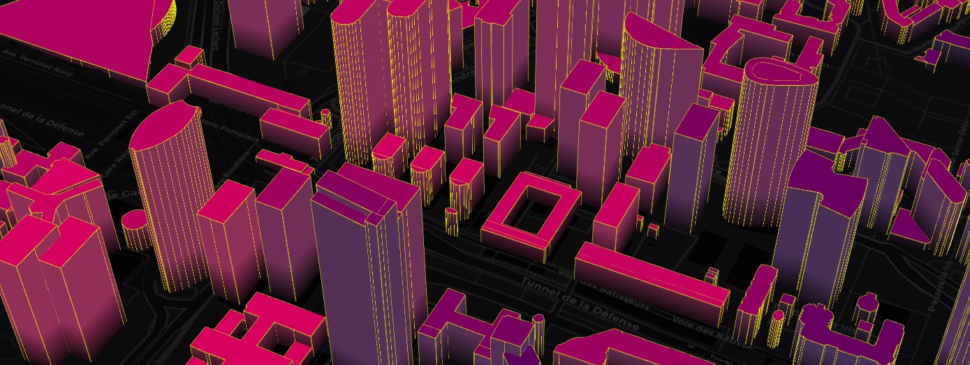
So if we want to modify (as static) the edges color lets change the color value to Yellow (255,255,0) with:
let ShadMatEdges = createMaterial(vertexShader, fragmentShader_edges, new THREE.Color(0xffff00));
See the result:
Let's see how it works inside the edges fragment shader around line 301
const fragmentShader_edges
It is a one line shader just attribuying the color we passed as a uniform parameter
gl_FragColor = vec4(color, opacity);
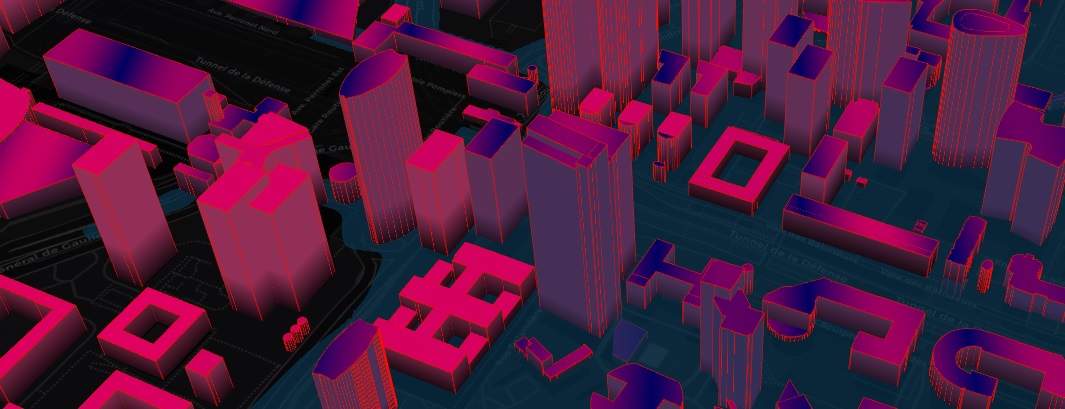
Let's try to make the color react to a uniform that the user modifies, for example the waterHeight (connected to the menu slider). We add a line of code that removes the green channel so it remains only the red (it was yellow (1.,1.,0.) before)
gl_FragColor.g = 1. - waterHeight / 60.;
See the result when moving the slider to the max (60):
Before we go back to shader implementation, note that you can more simply use THREEJS (the 3D library iTowns uses) material, they are many! (ex https://threejs.org/examples/?q=material#webgl_materials_bumpmap)
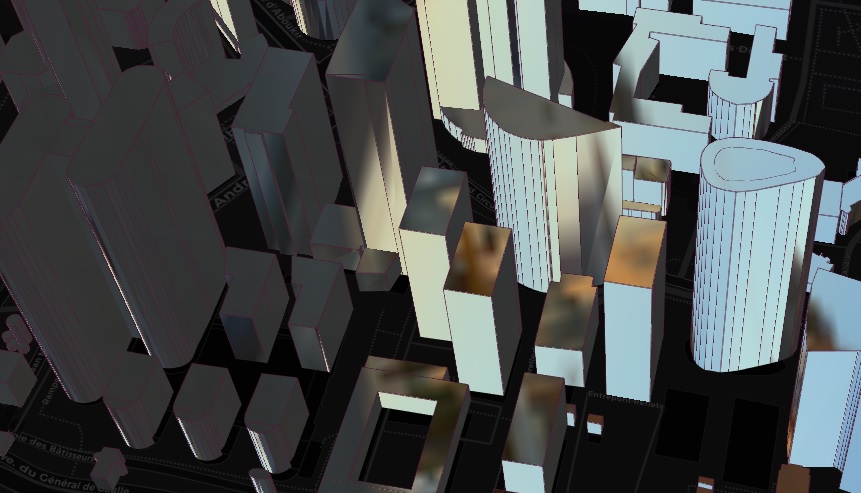
Look in the code around l370, I created a THREEJS material to create some reflection. Let's affect this material to the roof and walls instead of the previous custom one.
let ShadMatRoof = mat;
let ShadMatWalls = mat;
Here is the result:
If you look carefully the roof fragment shader around l297, we compare the height of the building bottom with the height of the water and change its color dynamically using the always updated time
if( vZbottom < waterHeight) gl_FragColor.r *= abs(sin(time + normUV.x ));
Now, let's say we want the roofs to flash in red when the water start to touch the building. We could do:
if( vZbottom < waterHeight) gl_FragColor.r = sin(time * 50.);
Using sinus is convenient to make a regular variation such as a flash. You can change the speed with the coefficient you apply.
As you can see in the demo, the building colors and geometry react to the mouse. This is done using picking on the terrain and on the buildings (around l441)
// Add 3D picking on both Terrain and Buildings
function addPickingCapability(){}
With these useful functions, we can compute the coordinate of the mouse in 3D. Note that you can remove the building pickings as it makes the framerate drop a bit.
We update the shaders with that 3D value so we can adapt the rendering, both in geometry and colors
ShadMatWalls.uniforms.currentPos.value = vec3; ShadMatRoof.uniforms.currentPos.value = vec3; ShadMatEdges.uniforms.currentPos.value = vec3;
Then in the shaders we compute the distance between the position of the current vertex and that 3D mouse coordinate and adapt the rendering. As this distance is computed in the Vertex Shader, in order to use it in the fragment shader we pass it as a varying we call dist (a variable that is shared between vertex and fragment shader).
Look the vertex shader (around l206):
dist = distance(posAbs.xyz, currentPos);
We can then change the geometry and color using this value.
The geometry:
if(dist < 200.) posAbs.xyz *= (1. + (200. - dist)/80000000.); // If mouse 3D intersection is close to building we push them up
The color:
if(dist < 200.) gl_FragColor = mix(gl_FragColor, vec4(0.,1.,0.,1.), 1. - dist / 200.); // We mix the current color with a green depending on the distance to the mouse
In the current demo, you can see by default the buildings close to the mouse turning. (You can set it off in the menu) If we look at the vertex shader responsible for this, we see that we compute the position of the mouse in the tile geometry. Let's understand all the transformation for the building geometry.
- The WFS (from IGN geoportal) serves the geometry in 2D as polygon with Z in geographic coordinates for each Tile (A tile is a square part of the ellipsoid composing our 3D earth)
- We compute the building boxes using triangulation
- We compute all the coordinates relative to the tile. (buildings coords have then very small value. Z is the height)
- In the vertex shader then, when we manipulate building vertices, remember that the variable position is a local coordinate, not in cartesian geocentric. To get the absolute coordinate you have to multiply it by the modelMatrix.
- In this example code we pass the absolute coordinate of the mouse to the vertex shaders so to get the distance with the vertices we can compute the mouse coordinate in the same reference as the vertices using the modelMatrix translation.
It is easy to understand using the itowns Debug mode (Menu: Debug camera or the best for this case LayerGlobe->SeeHelper that shows in orange the tile geometry under the mouse as you can see here:
- Make the buildings turn around the mouse (not like the example, as they turn around the center of their local coordinate system (tileGeometry))
It should look like this:

- Code a Jelly effect, in the spirit of https://hal.inria.fr/hal-01105179/document
It should look like this:

- Create an effect of fragmentation
For this, remember (or discover) that you can use the normals in the vertex shader! normal is an attribute passed by default. (ex vec3 newpos = normal * coef * position)
Playing with normals on faces can also create nice renderings as edges won't move

It should look like this:
