Assembly Instructions
At this stage you should have all your received all components, all parts printed and cleaned up, your electronics soldered and your software installed and tested.
The mechanical design consists of multiple subassemblies that are assembled first, with the final integration following.
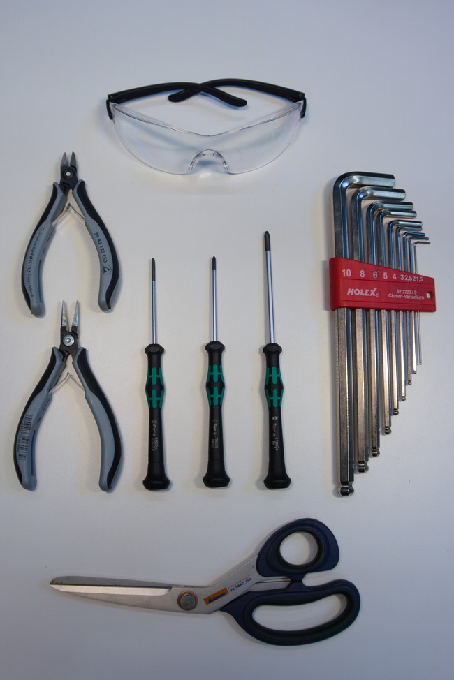
Necessary Tools
- Set of allen keys
- Small sized phillips screwdriver
- Medium sized phillips screwdriver
- Set of pliers
- Scissors
- Safety glasses
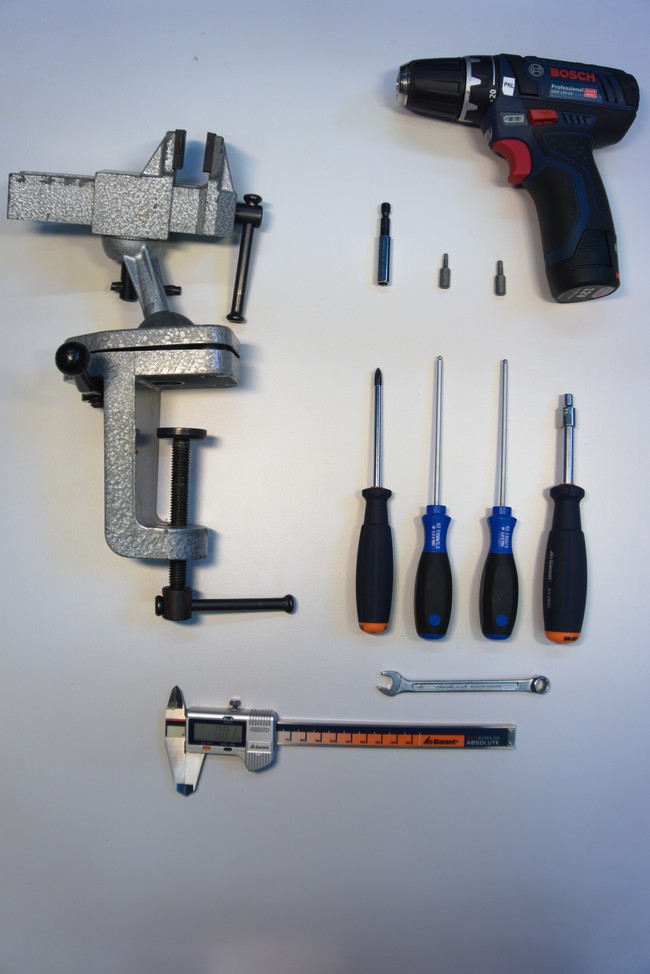
Optional Tools
The following tools are optional but can make the process easier and faster:
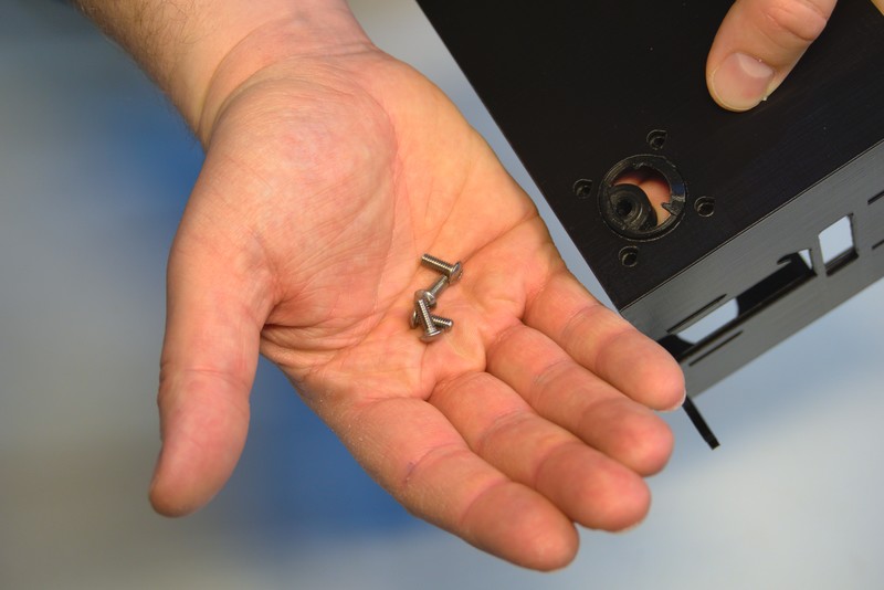
Required Parts:
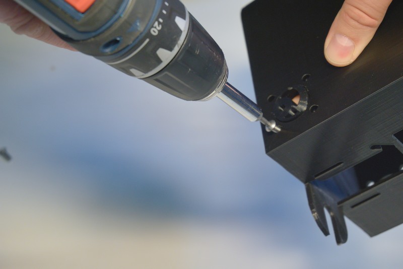
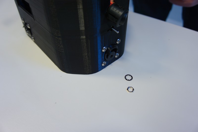
Make sure the threaded inserts are installed in the chassis as described here.
Start by installing the bogie bogie bearings with the M4x12 bolts into the chassis. Make sure they are oriented with the hole positioned on the bottom.
A drill can make the installation process faster. Be careful however not to over tighten the bolt as the thread can easily break.
Double check the orientation of the bogie bearings on all three. This would be very annoying to change later.
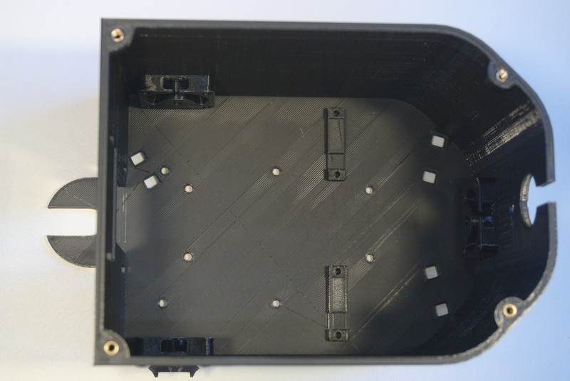
Look of chassis after installation of bogie bearings.
Now install the wire harness containing the switch, connectors and dc/dc convertors.
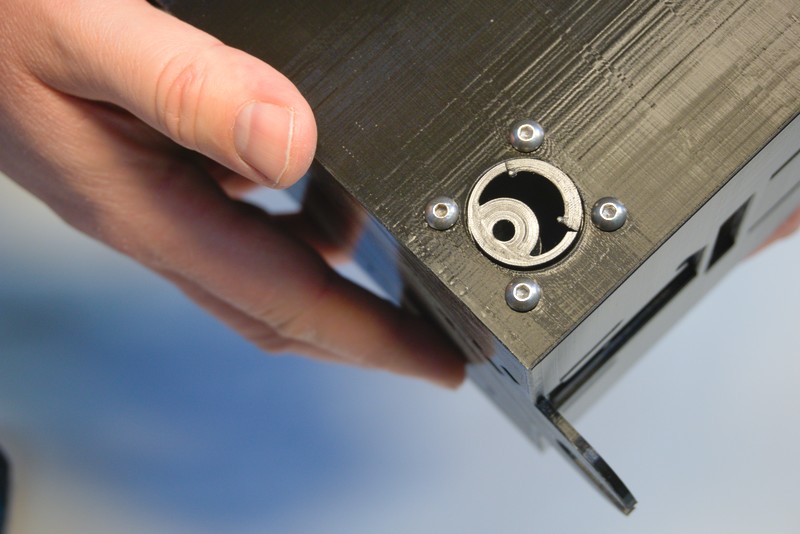
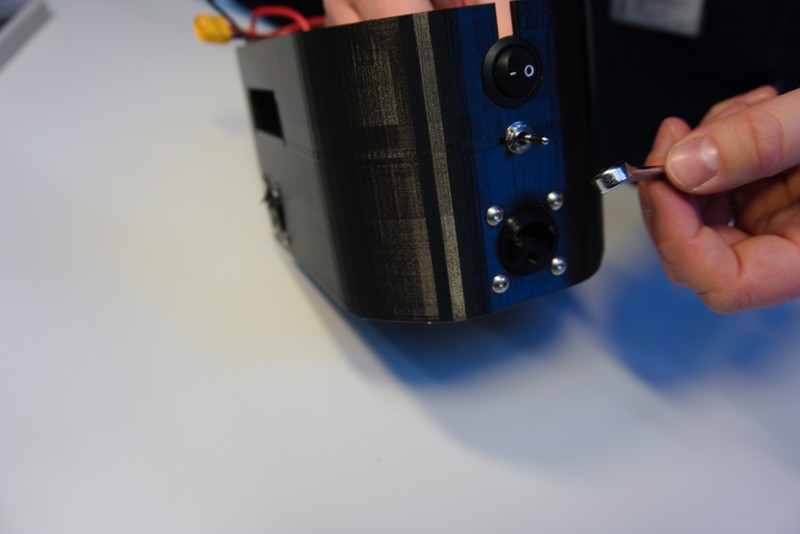
Start by inserting the power and motor switch into the chassis. Be aware of the notches that prevent the switch from rotating when installed.
 Use your spanner or pliers to tighten the motor switch nut.
 View after installation of switches.
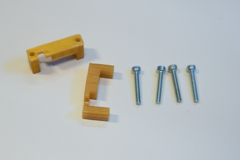
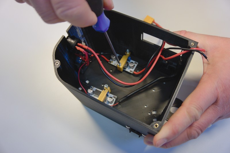
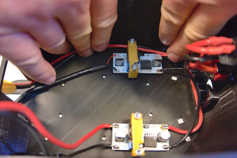
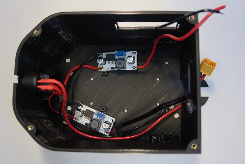 Next up is the installation of the DC/DC converters using the DC/DC hold down bracket and four M3x16 bolts shown bellow.
 Ensure that the adjustment screw of the DC/DC converter is still accessable and located in the dedicated cutout.
 Route the battery cable allong the right wall of the chassis and tighten the cables down with zip ties.
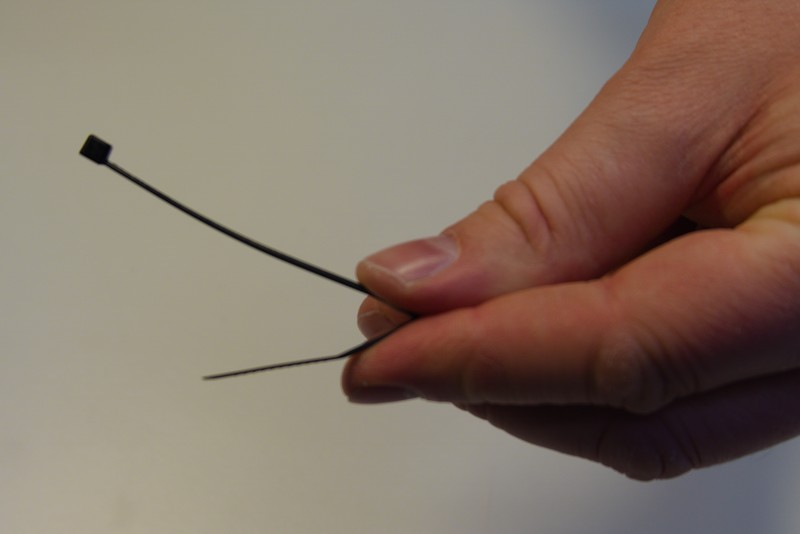
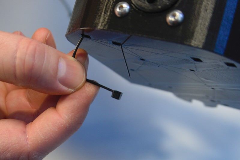
 Give the zip tie a kink before inserting it from the bottom in the three designated cutouts.
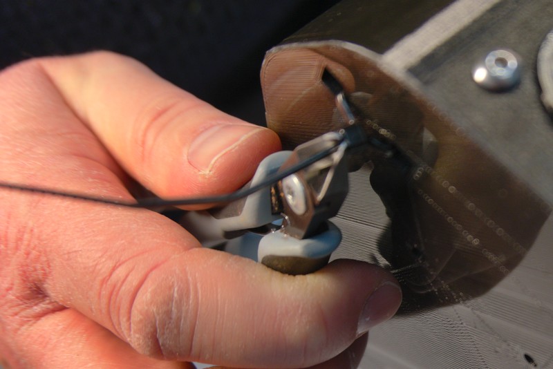
 Finally tighten and cut the zip ties.
 View of chassis after installation of the wire harness.
- Make sure to have the flanges oriented correctly.
- Don't press flange too hard on shaft for convenience.
- Leave Wheels out!
- Leave Camera out!
- Install Camera after top is mounted